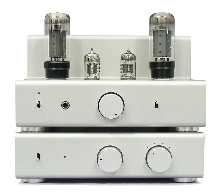
Upgrading TU8500
Many international audio forums includes a lot of information, how to upgrade/improve
sound of TU8500. Here you can find all suggestions in one place.
We can divide upgrades to visual and technical ones. Visual is simple for any skilled hobbyist. First worth doing is replacing an original front plate with custom made brushed stainless steel one. You have to carefully measure the U-shaped front plate and order laser cutting fo three flat parts - front, upper and lower. To make it easier, here are drawings with dimensions. Plates thickness should be 1.5mm
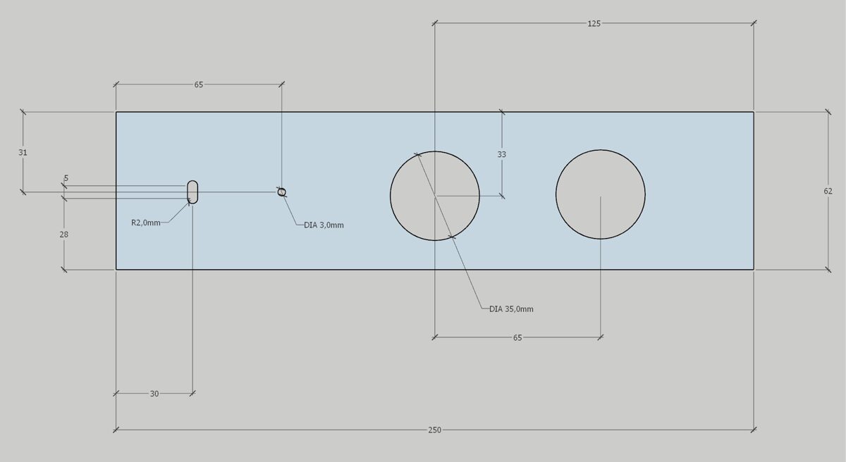
Front plate
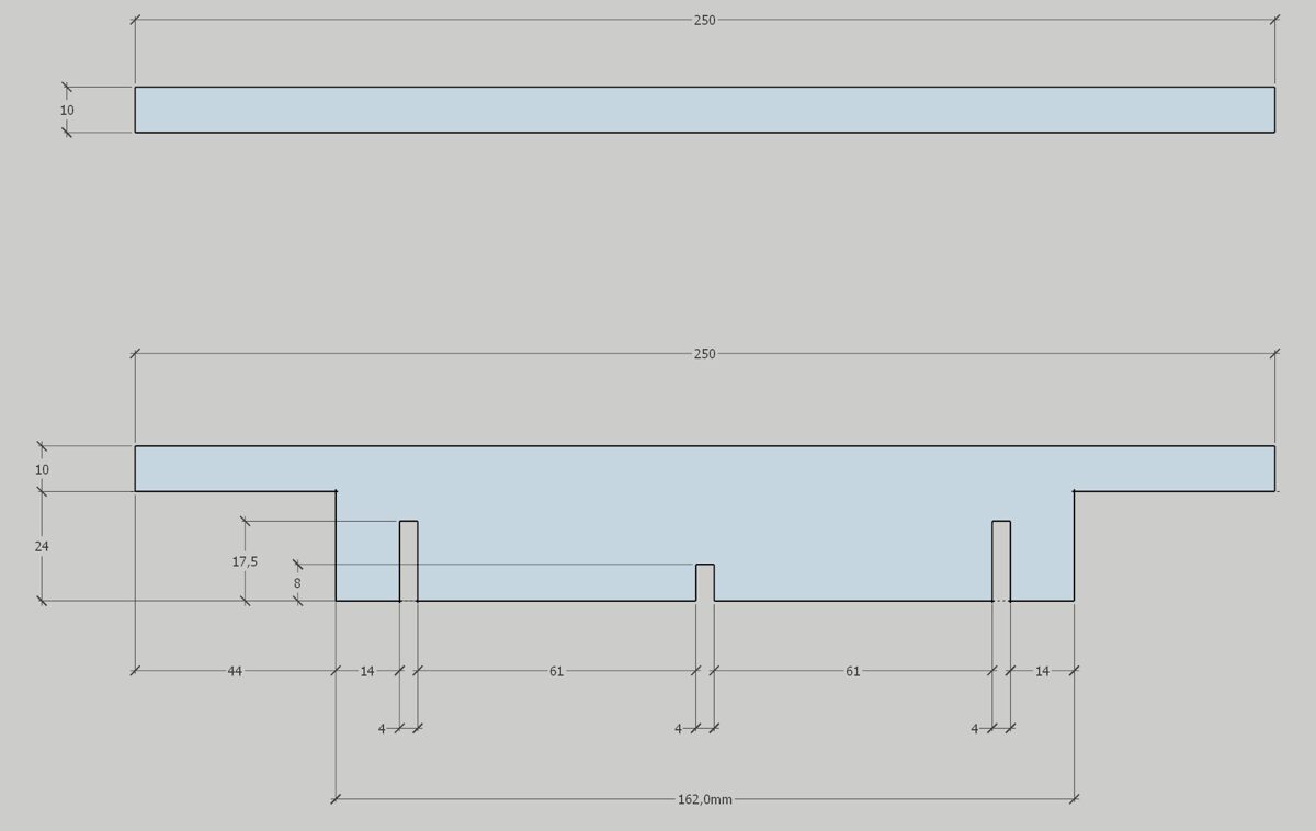
Top and bottom plate
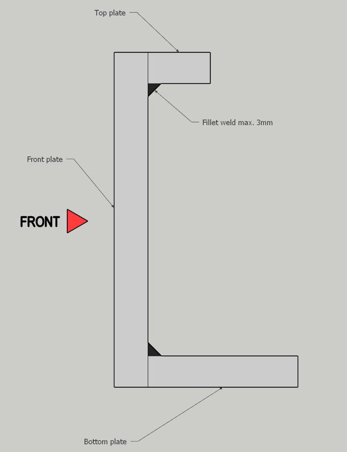
Last task is to weld all three plates - narrow top and bottom plate to the back of front plate - very carefully and precisely to maintain 90 degree angle between plates. Try to finish surfaces of plates before welding. Best sandpaper grit for brushing is 80. Below the drawing, how to weld plates to get proper fit to amplifiers.
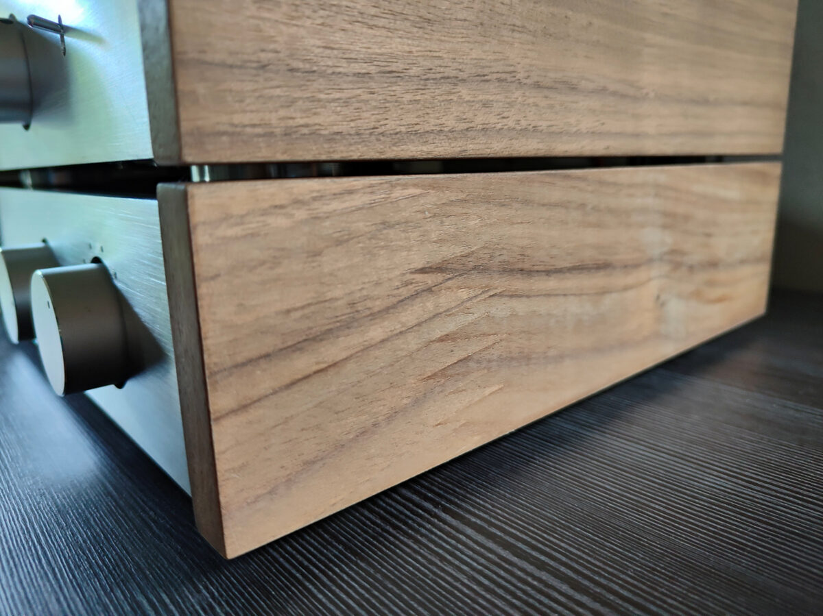
Second upgrade - making of wooden side panels. Buy two pieces of 12mm thick baltic birch plywood of size 256x66mm. Then buy some heat adhesive veneer. Cover carefully plywood with veneer and fix to the sides. Your choice if you will fix from outside or from inside. Each case anyway demands very careful positioning and drilling of holes in amplifier steel cover. Here you can see walnut veneer.
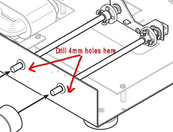
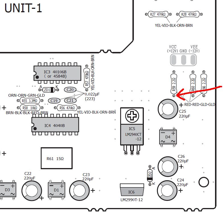
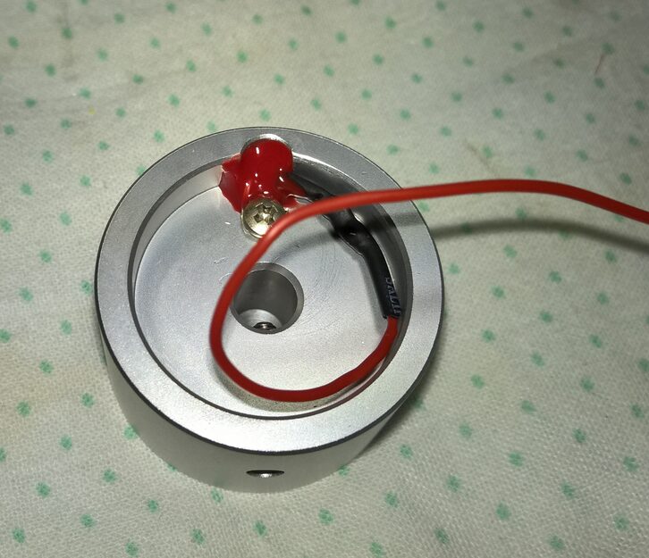
Last and trickiest part of visual upgrade is adding light to knobs and holes marking position of knobs in the front plate. Knobs have the holes from the back prepared to accomodate 5mm LEDs. You can buy any colour, I have choosen orange, as after adding the adequate resistors (you must decrease voltage from 12V to 3V or more) they lit nearly the same colour as tubes. To fit LEDs in those holes you will need to carefully remove small skirt at the bottom of plastic body. Then solder 10k ohms resistors to both orange 5mm LEDs cathodes, cover resistors with joints with shrink tube. Cathodes should be connected to the adequate spot. To do that you need to drill small holes (4mm) in the internal front plate, just side to the knob rods - you will guide wires through those holes. Cathodes should be connected to the spot before resistor R59. It is the point marked by red arrow.
 What about anodes (ground joint)? Each knob has a small hole just beneath a hole for LED. Bend anode 180 degree, put it inside the hole and solder here. Ready!
 Much more demanding task will be to add light to small holes, which mark positions of knobs. There are 2 holes at the bottom of volume knob and 4 holes above selector knob. But they are in the... original front! You do not have them, if you have made a new stainless front. So you have to carfully trace holes positions in your new stainless front and drill 1.5mm holes. Identical holes are positioned in internal front plate - both sets of holes have to match, when amplifier is fully assembled. Next task is to increase size of holes in internal plate to 3mm - to accomodate 3mm LEDs. Again - colour is your choice, I have choosen white.
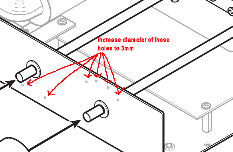 Now you have to make 6 sets of 3mm LEDs with 10k ohm resistor (or 1k if you want to have very bright spots) soldered to cathode and add around 15cm of thin cable to each resistor. Join all 6 cables to one at the end. Put all LEDs into extended holes, join cable end to the same spot at R59 resistor as you joined knobs cables. To ground all 6 anodes you can attach them together under ground screw in front right corner of the PCB (quite close to R59 resistor).
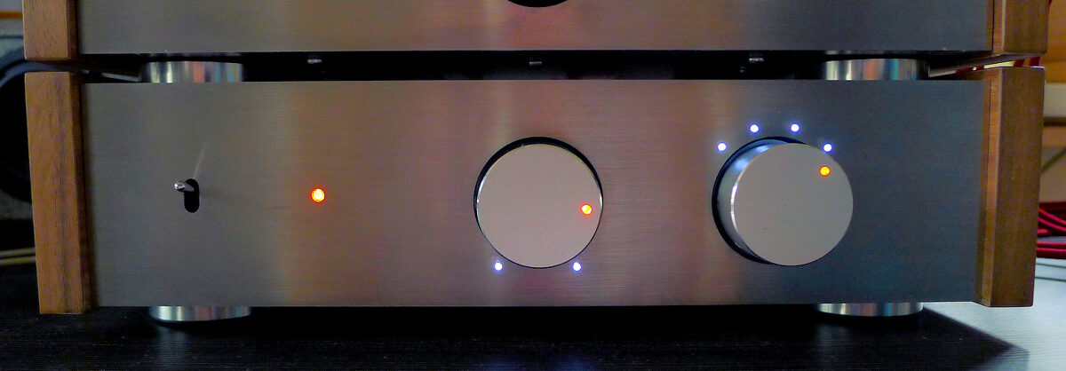
That is look after assembling stainless panel, veneered side panels and lights on TU8500. Photo is dark for purpose - lights are not strong and making photo with flashlight could cause unwanted reflexions.
...to be continued...